Article- Open Access
- Published:
A laser emitting contact lens for eye tracking
- A. Khaldi,
- E. Daniel,
- L. Massin,
- C. Kärnfelt,
- F. Ferranti,
- C. Lahuec,
- F. Seguin,
- V. Nourrit &
- J.-L. de Bougrenet de la Tocnaye
Scientific Reports volume 10, Article number: 14804 (2020) Cite this article
- 157 Altmetric
- Metricsdetails
Abstract
In this paper, we present the first realisation and experimentation of a new eye tracking system using an infrared (iR) laser pointer embedded into a wireless smart contact lens. We denote this contact lens prototype as the cyclops lens, in reference to the famous hero of the X-Men comics. The full eye tracker device combines the smart contact lens and its eyewear, which provides a primary source of energy and the beam detection system. We detail the assembling and encapsulation process of the main functionalities into the contact lens and present how a gaze tracking system is achieved, compared to existing conventional eye-tracking ones. Finally, we discuss future technical improvements.
Introduction
Knowing and analysing the gaze direction has become a key operation when using, for instance, augmented or virtual reality display systems for which it is useful to assess the attentional or cognitive load or to validate an operation by designating it by gaze1,2,3. Although a wide range of eye tracking techniques exist, these techniques are not always best suited to be used with an AR/VR headset. For instance, electro-oculography4 has limited accuracy, scleral-coils5 are uncomfortable requiring the eye to be anesthetized. Standard video-based techniques3 require a clear view of the eyes (e.g., glasses are an issue), small yet high aperture cameras and relatively high computing power, to provide a sufficiently high accuracy. As a result, the issue of integrating a performing eye tracker into an AR/VR headset is still an active research topic6,7.
In parallel, encapsulation of functions in a wireless contact lens has been made possible thanks to recent advances in technologies for manufacturing micro-scale optoelectronic components, as well as methods for assembling them onto separately-formed substrates8,9. As a result, a variety of electronic contact lenses have been proposed in the last two decades. Due to the nature of the lens, the applications concern mainly wearable smart sensors for health diagnostics10,11, the correction of vision or refractive errors12, gaze tracking13 or displays14,15,16,17. Some wireless contact lenses have been tested on persons (e.g. studies carried out at Moorfields Eye Hospital in London18) and have been commercialized in medical products (e.g., Sensimed19). However, their overall functions were relatively specific (e.g., intraocular pressure gauge (IOP) or glucose monitoring) they operated as interrogators and did not implement complex cognitive tasks. In this context, including a laser pointer directly on the eye could provide a potentially simpler and more compact solution to measure eye gaze compared to available technologies based mostly on image processing20,21. It would also allow demonstrating the use of an electronic contact lens as component of a more complex system (eye tracking).
The operating principle of the eye tracking system is described below. The idea to use a marker into a contact lens is not new22 and neither the integration of a light source into a contact lens. The integration of a micro-LED has already been demonstrated for other applications [e.g.23]. We propose here to use a vertical cavity surface emitting laser (VCSEL) because of the good ratio between the laser power and the power supplied as well as the very low divergence (few tens of mrad without any additional optics) which allows for a high quality beam spot (necessary here to get a good detection accuracy). Our goal was here to scale all the elements to design and realize a complete eye tracking system, showing how the spot emitted by a laser pointer can be detected correctly by the sensor (independently from the eye rotation) with a good accuracy, for a given distance between the eye and the eyewear, and in compliance with the security standards (optical and RF).
Eyetracking operating principle
The idea here consists in encapsulating a laser pointer or a light emitting source24 into a contact lens to materialize the direction of gaze, therefore strongly simplifying its calculation. Most commercial eye trackers rely on imaging the eyes. This involves illuminating the eyes with IR light sources, recording several MB of information/s with fast cameras and processing this information to extract, from the pupil and corneal reflection position, the gaze direction at high frequencies. As stated previously, a number of factors such as iris pigmentation, wearing spectacles, sunlight can reduce such eye tracker performance. Other approaches such as electrooculography or lenses with magnetic coils exist but their implementation makes them suitable only for research or clinical studies25. Indeed, these two techniques, as the cyclops lens, require some preparation (fitting the lens, the electrodes or the coils) and are more invasive than the video based eye trackers. When compared to the scleral coil approach, the main advantage of the cyclops lens is that there are no external parts. All the electronics is embedded within the lens. Electrooculography can be useful in some context (e.g. when the eyes are closed) but offer limited resolution3 (~ 2°) and are sensitive to various factors (facial muscle activity, electrical interferences, etc.) that limit its use.
In our system, detecting the laser beam direction will directly provide the gaze direction. This can be achieved in different ways. A solution consists in using a 2D planar detector26 such as a position sensitive detector (PSD). In this case, the remote control system is replaced by the eye, provided that a collimated laser with a sufficient light power to be detected by the PSD is used, in case this one is far from the lens.
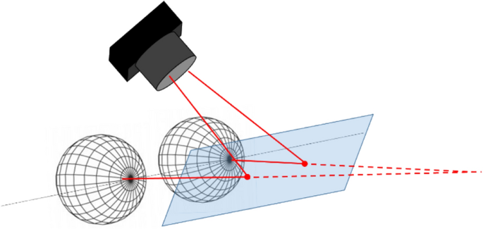
Using a PSD enables, in a simple way, to detect several spots together (in contrast to complex image processing) so, that for each eye equipped with a laser pointer contact lens, it becomes possible to extract the vergence angle and then to deduce the sight direction knowing the eye’s position. Transparent PSD (transparent for the eye while sensitive (absorbent) for the laser beam; the wavelength being chosen in any case out of the visible range) could be manufactured, at the cost of a more complex optimisation of the substrate27. A simple alternative to a transparent PSD consists in using a beam splitter (BS) as shown in Fig. 1 together with an IR camera. This beam splitter is coated to reflect the IR beams generated by the two laser spots while being transparent for the eyes and coated to avoid unwanted reflections. Furthermore, it enables to materialize the beams (since it intercepts it, cf. Fig. 1 so that a single IR camera can be used to detect the spot motions on the BS surface. We use an IR camera (ELP Full HD 1920 × 1080 p) for our demonstration. In this case, a very elementary software can be developed either to detect the direction of sight or to track the eye trajectories.
In the following section, we present how to make the Cyclops lens and how the energy transfer towards the laser pointers is performed to obtain a very compact prototype.
